


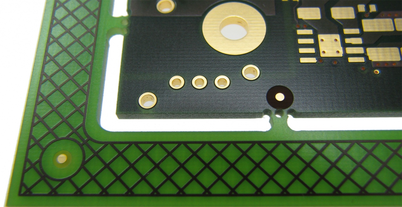
A PCB is more than a collection of copper traces, pads, vias, and components. The information printed on the board also plays an important role in assembly, inspection, testing, servicing, and identification. This printed information is commonly known as the PCB silkscreen.
Silkscreen can identify component references, connector locations, polarity indicators, test points, logos, warnings, and other useful information. When properly designed, it improves board readability without interfering with electrical or mechanical features.
However, silkscreen markings must follow practical rules for text size, line width, clearances, placement, and manufacturability. A poorly designed silkscreen can become difficult to read or may overlap pads and other conductive features. Following appropriate silkscreen pcb practices can improve component identification and manufacturing clarity.
What Is PCB Silkscreen?
PCB silkscreen is a printed layer used to place visual information on a circuit board. It is typically applied to the component side and, when required, the solder side of the PCB.
Common silkscreen information includes:
- Component reference designators
- Pin 1 indicators
- Polarity markings
- Connector labels
- Switch positions
- Test-point identifiers
- Warning labels
- Assembly instructions
- Product identification
- Company logos
- Revision information
The silkscreen does not normally serve as an electrical conductor. Its primary purpose is to provide visual information to people working with the PCB.
Common PCB Silkscreen Colors
White is one of the most commonly used silkscreen colors, particularly on green solder-mask boards. Other colors can also be available depending on the PCB manufacturer’s process and material options.
The selected silkscreen color should provide sufficient contrast against the solder mask so that markings remain readable after manufacturing.
Color availability and printing characteristics vary between manufacturers, so the fabrication house should be consulted when a specific color or appearance is important.
PCB Silkscreen Sizes
Text size is one of the most important considerations in silkscreen design.
Extremely small text may become difficult to print accurately and may lose characters during manufacturing. Extremely large text can consume valuable board space and interfere with component placement.
A practical silkscreen specification commonly considers:
- Character height
- Character width
- Stroke width
- Font type
- Line thickness
- Spacing between characters
The manufacturer’s minimum specifications should always take priority because different fabrication processes support different minimum dimensions.
Recommended Text Size
There is no single universal silkscreen text size suitable for every PCB manufacturer. However, designers often use text around 1.0mm or larger in character height when board space permits.
Smaller text may be possible with certain manufacturing processes, but readability and production yield should be evaluated.
For critical identifiers, using a slightly larger font can make inspection and servicing easier.
Silkscreen Line Width
Silkscreen graphics and characters are created using printed lines. If those lines are too thin, they may become inconsistent or disappear during fabrication.
A commonly used starting point is around 0.15mm to 0.20mm minimum stroke width, but the exact limit depends on the PCB manufacturer’s capabilities.
Designers should obtain the manufacturer’s current silkscreen specifications before finalizing detailed artwork.
Silkscreen Clearance
One of the most important silkscreen rules is maintaining sufficient clearance from solderable areas.
Silkscreen printed over a component pad can contaminate the soldering area or obscure the pad during assembly and inspection. PCB manufacturers often automatically clip silkscreen from pads, but relying entirely on automatic removal can produce unexpected results.
Designers should maintain the manufacturer’s recommended clearance between silkscreen and:
- SMD pads
- Through-hole pads
- Via pads where relevant
- Exposed copper
- Component bodies
- Mechanical features
The required clearance varies by manufacturer and assembly process. Following appropriate PCB silkscreen and legend rules can improve component identification and assembly accuracy.
Advantages of a Well-Designed PCB Silkscreen
- Easier Component Identification
Reference designators make it easier for assembly operators, engineers, and technicians to identify components on the finished board.
- Faster Assembly
Clear component markings can help assembly personnel locate components and understand their intended positions.
- Improved Inspection
Silkscreen labels and polarity indicators can make visual inspection more efficient by providing additional information about component orientation and placement.
- Easier Troubleshooting
Technicians can identify components, connectors, and test points more quickly when reference information is clearly printed on the board.
- Better Maintenance
Readable markings can remain useful throughout the product’s service life, particularly when documentation is not immediately available.
- Improved Product Identification
Board names, revision numbers, serial information, and logos can help identify a PCB during manufacturing, inventory, testing, and field servicing.
- Reduced Assembly Errors
Clear polarity, orientation, and component-location markings can help reduce mistakes during manual assembly and rework.
PCB Silkscreen Design Rules
Rule 1: Keep Silkscreen Away From Pads
Avoid placing important silkscreen information directly over solderable pads.
If a reference designator must pass near a pad, adjust its position or use the manufacturer’s recommended clearance.
Rule 2: Use Readable Fonts
Choose simple PCB-compatible fonts rather than highly decorative typefaces.
Characters should remain distinguishable after printing and should not contain unnecessarily narrow features.
Rule 3: Maintain Adequate Stroke Width
Use a line width that is compatible with the manufacturer’s minimum silkscreen specification.
Thin strokes can break up or become difficult to read.
Rule 4: Avoid Component Overlap
Silkscreen should clearly communicate component locations without being hidden beneath components.
For example, placing a reference designator directly underneath a large IC package may make it invisible after assembly.
Rule 5: Mark Component Polarity
Diodes, LEDs, electrolytic capacitors, and other polarized components can benefit from clear polarity indicators.
Pin 1 indicators are also useful for ICs, connectors, and other components where orientation matters.
Rule 6: Label Connectors Clearly
Connector labels such as input, output, power, communication, or signal names can improve usability and reduce connection errors.
Rule 7: Keep Critical Information Visible
Reference designators and important orientation marks should remain visible after components are installed whenever practical.
Rule 8: Consider Board Edges
Keep silkscreen away from areas where board-edge cutting, routing, beveling, or mechanical processing could affect the printed information.
Rule 9: Avoid Excessive Graphics
A PCB can become visually cluttered if too many logos, decorative graphics, and unnecessary labels are included.
Use the available silkscreen area efficiently and prioritize information that supports assembly and service.
Rule 10: Check Both Sides
If silkscreen is used on both sides of the PCB, review the top and bottom layers independently.
Make sure markings are correctly oriented and do not conflict with components, pads, mounting hardware, or other mechanical features.
Silkscreen and Reference Designators
Reference designators are among the most useful pieces of information on a PCB.
Examples include:
- R1 for resistors
- C1 for capacitors
- U1 for integrated circuits
- D1 for diodes
- L1 for inductors
- J1 for connectors
- TP1 for test points
The exact reference-designator conventions depend on the design documentation and engineering standards used by the project.
Reference designators should be positioned so that technicians can associate each label with the correct component.
Silkscreen for Component Orientation
Orientation markings are particularly useful during assembly and repair.
A small dot, line, triangle, notch representation, or other suitable symbol can identify Pin 1 or another orientation reference.
For polarized components, positive and negative indicators can also be printed where appropriate.
These markings should be positioned so they remain visible and unambiguous after assembly.
Silkscreen vs Solder Mask
Silkscreen and solder mask serve different purposes.
Solder mask is an insulating coating that protects selected PCB copper areas and helps prevent solder bridges.
Silkscreen is a printed information layer used primarily for identification and visual guidance.
A silkscreen layer should therefore not be treated as a substitute for electrical insulation, creepage protection, or other PCB safety measures unless a specific standard explicitly recognizes the relevant material and construction.
Silkscreen and Automated Assembly
Although silkscreen is primarily intended for human-readable information, its quality can indirectly support automated assembly processes by making component locations and orientations easier to verify.
For automated optical inspection, however, the primary inspection information comes from the PCB design data, component characteristics, and inspection system. Silkscreen should not be considered the sole source of assembly information.
Designing Silkscreen for Manufacturing
The best silkscreen designs consider manufacturing capabilities from the beginning.
Before completing the PCB layout, designers should obtain the PCB manufacturer’s fabrication rules. These may specify:
- Minimum text height
- Minimum stroke width
- Minimum silkscreen-to-pad clearance
- Supported fonts
- Line and graphic limitations
- Registration tolerances
- Color options
Following these specifications can reduce unwanted clipping, missing characters, and unreadable markings.
Common Silkscreen Problems
Text Over Pads
Text printed over solder pads may be removed during fabrication or may interfere with assembly.
Text Hidden Under Components
A reference designator placed beneath a large component may become inaccessible after assembly.
Very Small Characters
Small text may lose clarity during manufacturing or become difficult for technicians to read.
Thin Lines
Lines below the manufacturer’s supported width can become incomplete or inconsistent.
Incorrect Orientation
Poorly positioned polarity or Pin 1 markings can create confusion during assembly and repair.
Excessive Information
Too many labels can make the PCB difficult to read and reduce the usefulness of important markings.
A Practical Silkscreen Design Workflow
A simple design process can help produce a clean and manufacturable result:
- Obtain the PCB manufacturer’s silkscreen design rules.
- Establish minimum text height and stroke width.
- Place essential reference designators first.
- Add polarity and orientation indicators.
- Label important connectors and test points.
- Add board identification and revision information.
- Check silkscreen-to-pad clearances.
- Move markings that will be hidden by components.
- Remove unnecessary decorative information.
- Run the PCB design-rule check and review the final fabrication output.
Final Considerations
PCB silkscreen may appear to be a minor part of circuit-board design, but well-planned markings can provide significant practical benefits throughout manufacturing, inspection, assembly, testing, troubleshooting, and maintenance. A detailed PCB fabrication drawing guide can help engineers prepare clearer manufacturing documentation for PCB suppliers.
The most effective silkscreen is clear, readable, correctly positioned, and compatible with the manufacturer’s printing capabilities. Designers should pay particular attention to text size, stroke width, pad clearance, component visibility, polarity markings, and board-edge restrictions.
By incorporating silkscreen requirements into the PCB layout process rather than treating them as an afterthought, engineering teams can create boards that are easier to assemble, inspect, identify, and service.
